Peerless Labelled Diagram Of Dc Motor
Generally copper bars form.
Labelled diagram of dc motor. Invisible magnetic field. Accordingly the armature and field current are equivalent. Dc motors are seldom used in ordinary applications because all electric supply.
We can represent it by the block diagram shown below. It is a controlled rectifier since the voltage to frequency ratio of the power supplied to an induction motor is a constant. Torque t and speed ω from the mechanical port or output port.
Like generators there are different types of dc motors which are also classified into shunt wound series wound and compound wound dc motors. Huge current supply straightly from the supply toward the field windings. The direction of rotation is reversed by inverting one or.
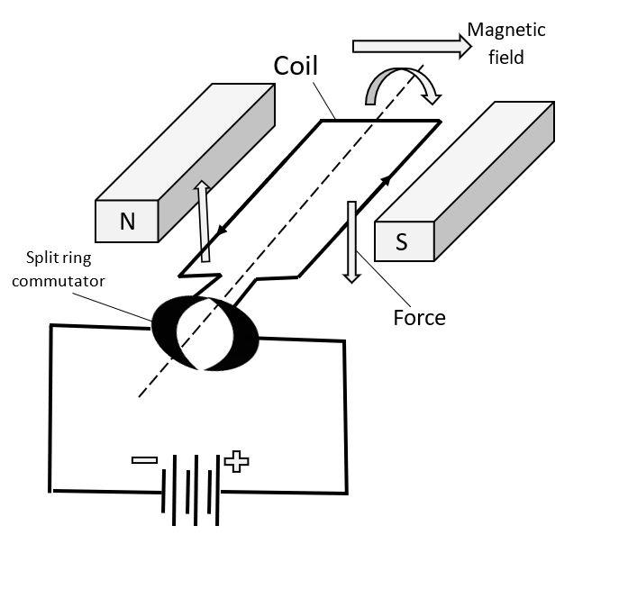
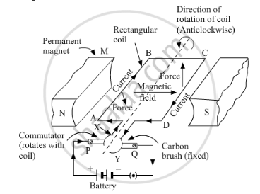
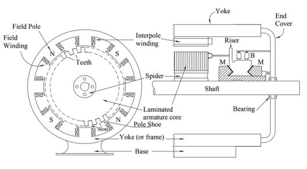
The very basic construction of a dc motor contains a current carrying armature connected to the supply end through commutator segments and brushes. The controlled rectifier functional block converts ac to dc. There is no basic difference in the construction of a dc generator and a dc motor.
Figure 3 diagrams of the various types of dc motor. What is the role of the split ring in an electric motor. As soon as we supply direct current in the armature a mechanical force acts on it due to the electromagnetic effect of.
The armature carrying current provided by the battery is an electromagnet because a current carrying wire generates a magnetic field. The huge current can be carried by field windings because these windings have few turns as well as very thick. Parallel excitation separate or shunt the coils armature and field coil are connected in parallel or supplied via two sources with different voltages in order to adapt to the characteristics of the machine e g.


