Looking Good 3 Pin Rocker Switch Wiring Diagram

Imstricken06 imstricken06commonly tools used milwaukee impact.
3 pin rocker switch wiring diagram. Lines in the diagram show exactly how every element connects to a another. The first element is symbol that indicate electric element from the circuit. However it doesn t imply link between the cables.
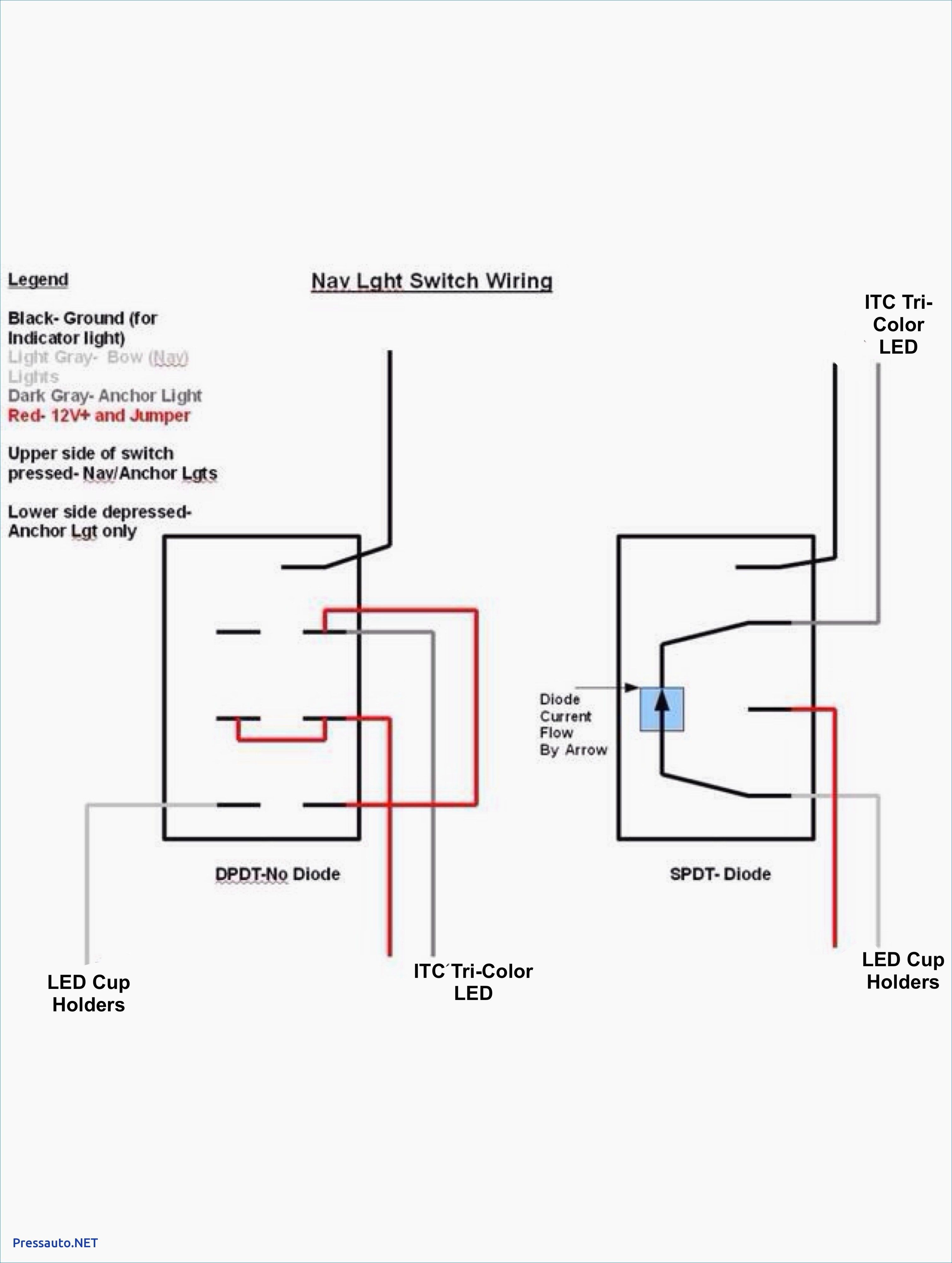
The diagram below represents the schematic diagram for a spst rocker switch. As stated previous the traces at a 3 pin rocker switch wiring diagram signifies wires. For the led rocker switch pay careful attention to the position of your ground power and acc pins follow the diagram below it uses oznium s led round rocker switch with recommended mounting hole diameter of 3 4 and you should have no problems wiring a led rocker switch.
Components of 3 pin rocker switch wiring diagram and some tips. An illuminated rocker switch is like a spst toggle switch with an extra terminal which allows the light to work. Led rocker switch wiring diagram.
Most rocker switches are of the single position. Injunction of 2 wires is generally indicated by black dot at the junction of two lines. This video is showing how to wire a rocker toggle switch with a led indication light.
Pin 3 is where the switch is either connected to ground or left open. Sometimes the cables will cross. A circuit is generally composed by numerous components.
Pin 2 is where the accessory that the switch is going to turn on is connected. We have wiring diagrams and wiring guides on how to wire a 10 terminal nav ancher on off on 3 way carling contura rocker switch as well as a wiring diagrams in how to wire a 10 terminal bilge auto manual on off on 3 way carling contura rocker switch for more on how to wire a bilge pump check this out we also have a general dpdt wiring diagram for powering two loads using an on off on 3 way. You might want to review the article on toggle switch wiring before proceeding.


